WHAT IS COUPLING?
Today, in a technological competitive environment, manufacturers can only increase their quality as they specialize in their own fields, and they can renew their business volumes as they do in-depth research on that subject. For this reason, engine manufacturers only produce engines, pump manufacturers only pumps, compressor manufacturers manufacture compressors; The coupling is needed to connect the electric motor manufactured in a specialist firm to a pump manufactured in another specialist firm. Of course, this coupling manufacturer is also expected to be an expert.
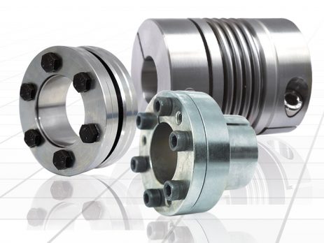
The coupling is the element of transferring the rotational movement and thus the moment produced in a power source to another system (machine, pump, reducer, conveyor etc.). A coupling that performs this task is also:
1-It should not cause malfunction due to power loss or unbalance.
2-It should not pass the vibrations and knocks that may occur in the system to the engine behind.
3-When the system malfunctions due to jamming or breakage, it should break and act as an insurance to protect the engine.
4-As long as the system operates normally, it should be dimensioned, designed and manufactured from suitable materials without breaking for many years and requiring minimum maintenance.
WHERE TO USE
AXIAL FREQUENCY
ANGLE FREQUENCY
HORIZONTAL LEAKAGE
HOW TO MAKE COUPLING SELECTION?
1-Coupling Size Selection
The torsional moment produced by a motor or a motor-driven gear unit is calculated by the formula:
Torsional moment = (Motor Power / Rotation speed of the shaft where coupling is needed) x 9550
In this formula, 9550 is a fixed number
Engine power taken in kilowatts
The rotation speed of the spindle is the number of revolutions per minute
The unit of the torsional moment is obtained in nM (Newton meters).
Coupling is needed not only at the motor output, but sometimes at the reducer output, at this point, the motor power and the speed after being reduced several times should be formulated in the calculation of the torsional moment produced.
The coupling to be selected should be able to meet a torsion moment higher than the torsion moment found in the formula above, because when the coupling is running, the system stops and lifts too much or the environment is too hot or the system’s excessive pulsation shortens the life of the coupling. Multiplied by the moment, it reveals the TORQ that the coupling must bear.
TORQ = Torsional moment x A x B x C
The working coefficients given in the formula with the letters A, B, C are given numerically as a result of the experiences and the user can find TORK by choosing the appropriate number for the environment and working conditions.
TORQ values that can be carried by the couplings we manufacture in our company are tested in accordance with DIN 740 norm and stated in the dimension tables. The user will be able to easily select the coupling based on the TORK value above the TORK value he finds while selecting the coupling he needs. When making this selection, he should also make sure that the motor or reducer shaft is smaller than the maximum shaft diameter given in the table as d (max).
Today, in a technological competitive environment, manufacturers can only increase their quality as they specialize in their own fields, and they can renew their business volumes as they do in-depth research on that subject. For this reason, engine manufacturers only produce engines, pump manufacturers only pumps, compressor manufacturers manufacture compressors; The coupling is needed to connect the electric motor manufactured in a specialist firm to a pump manufactured in another specialist firm. Of course, this coupling manufacturer is also expected to be an expert.
The coupling is the element of transferring the rotational movement and thus the moment produced in a power source to another system (machine, pump, reducer, conveyor etc.). A coupling that performs this task is also:
1-It should not cause malfunction due to power loss or unbalance.
2-It should not pass the vibrations and knocks that may occur in the system to the engine behind.
3-When the system malfunctions due to jamming or breakage, it should break and act as an insurance to protect the engine.
4-As long as the system operates normally, it should be dimensioned, designed and manufactured from suitable materials without breaking for many years and requiring minimum maintenance.
WHERE TO USE
AXIAL FREQUENCY
ANGLE FREQUENCY
HORIZONTAL LEAKAGE
HOW TO MAKE COUPLING SELECTION?
1-Coupling Size Selection
The torsional moment produced by a motor or a motor-driven gear unit is calculated by the formula:
Torsional moment = (Motor Power / Rotation speed of the shaft where coupling is needed) x 9550
In this formula, 9550 is a fixed number
Engine power taken in kilowatts
The rotation speed of the spindle is the number of revolutions per minute
The unit of the torsional moment is obtained in nM (Newton meters).
Coupling is needed not only at the motor output, but sometimes at the reducer output, at this point, the motor power and the speed after being reduced several times should be formulated in the calculation of the torsional moment produced.
The coupling to be selected should be able to meet a torsion moment higher than the torsion moment found in the formula above, because when the coupling is running, the system stops and lifts too much or the environment is too hot or the system’s excessive pulsation shortens the life of the coupling. Multiplied by the moment, it reveals the TORQ that the coupling must bear.
TORQ = Torsional moment x A x B x C
The working coefficients given in the formula with the letters A, B, C are given numerically as a result of the experiences and the user can find TORK by choosing the appropriate number for the environment and working conditions.
TORQ values that can be carried by the couplings we manufacture in our company are tested in accordance with DIN 740 norm and stated in the dimension tables. The user will be able to easily select the coupling based on the TORK value above the TORK value he finds while selecting the coupling he needs. When making this selection, he should also make sure that the motor or reducer shaft is smaller than the maximum shaft diameter given in the table as d (max).
Bir cevap yazın